Web Based Remote Monitoring
Reliable Web based solutions for monitoring the condition or status of remote assets no matter where you or they are located.
Read more...

![]()
Instrument PSUs

Priced to perfection
DIN Rail mounted
All Round Protection
Adjustable 24Vdc o/p
FOR IMMEDIATE RELEASE
The ubiquitous problem with every plant is the interface of plant measurement signals to the monitoring and control systems. Unfortunately for many plants this is the single biggest area of weakness and with the success of the organisation depending on these measurements, more attention should be afforded to the integrity of signal conditioning systems.

1. Your analog input does not support 4-20 mA, and mounting an external resistor is inconvenient.
2. Your analog input has plug in terminals, and you do not want to lose power to your field transmitter or disrupt the loop if the terminal block is unplugged.


In these cases you can use the internal resistor on the OUT side of the LPI to conveniently convert your 4-20 mA signal into a 1-5 V signal.
For the most accurate result, ensure that the 0V reference to the LPI (terminal 5), and the 0V reference of your analog input are referenced to the same point.
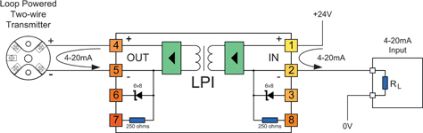
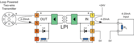
Note: The 'IN' side of the LPI is always connected to the side of the loop supplying the loop power, so in this application the four-wire transmitter is connected to the IN terminals of the LPI.
Because of the 2 mm² wire size capability of the LPI terminals, the LPI can also act as the field interface terminals, saving you the extra termination and wiring cost.
The LPI will consume less than 8 V of the available loop voltage. This is equivalent to inserting less than 400 Ω of resistance into the current loop.
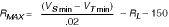
To determine the maximum loop resistance that you can tolerate in your cabling in this application, apply the following formula:
RMAX = RT - 400
where:
RMAX is the maximum resistance in the loop without causing measurement error (in Ω).
RT is the maximum load resistance that the current transmitter can drive (in Ω).
For reliable operation over the long term, you should design for less initial cable resistance than this maximum value. This provides a safety factor to account for increase in resistance of terminations and wiring with age or weathering.
A sensible value to use for this safety factor would be 100 Ω (equal to 2 V at 20 mA).


In these cases you can use the internal clamp of the LPI to protect the loop from open circuit if your PLC or RTU or DCS input is unplugged or disconnected.
In four-wire current transmitter applications this is simply achieved by connecting the output clamp terminal 6 to the current output terminal 4 of the LPI. If the analog input to your PLC or RTU or DCS is disconnected, the current will be diverted through the clamp, saving the current loop from disconnection.
The voltage across the LPI will be clamped to 6,8 V in this condition - slightly higher than the normal operating voltage of 1-5 V. This higher clamp voltage should be used when calculating maximum allowable loop resistance.
Note: The 'IN' side of the LPI is always connected to the side of the loop supplying the loop power, so in this application the four-wire transmitter is connected to the IN terminals of the LPI.
Because of the 2 mm2 wire size capability of the LPI terminals, the LPI can also act as the field interface terminals, saving you the extra termination and wiring cost.
To determine the maximum loop resistance of your cabling that you can tolerate in your loop with the clamp in operation, apply the following formula:
RMAX = RT - 500
where:
RMAX is the maximum resistance in the loop without causing measurement error (in Ω).
RT is the maximum load resistance that the current transmitter can drive (in Ω).
For reliable operation over the long term, you should design for less initial cable resistance than this maximum value. This provides a safety factor to account for increase in resistance of terminations and wiring with age or weathering.
A sensible value to use for this safety factor would be 100 Ω (equal to 2 V at 20 mA).
For more information on the LPI, click here.
Application 7: Using the LPD to isolate multiple 4-20 mA outputs from a PLC or DCS
In this application, the LPD can be inserted directly into the 4-20 mA output loops between the transmitter and the load.


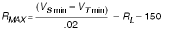

where:
RMAX is the maximum resistance in the loop without causing measurement error (in Ω).
VSmin is the minimum voltage of the power supply used to drive the loop (in V).
VTmin is the minimum voltage required by the two-wire transmitter for operation (in V).
RL is the resistance of the PLC/RTU input (in Ω).
For reliable operation over the long term, you should design for less initial cable resistance than this maximum value. This provides a safety factor to account for increase in resistance of terminations and wiring with age or weathering.
A sensible value to use for this safety factor would be 100 Ω (equal to 2 V at 20 mA).
For more information on the LPD, click here.
Application 10: Dealing with zero loop resistance when using the LPI
The LPI is optimised to minimise the effective inserted loop impedance, but does require a minimum of 100 Ω of load impedance, (or 2 V) on the output to maintain operation.

In some applications, when using four-wire transmitters, the load being driven is lower than this minimum value, and additional load needs to be inserted into the output loop to bring the minimum load up to the required 100 Ω.
One solution for this is to use the internal 250 Ω resistor to provide this additional resistance. When connected as shown in the diagram, the internal resistor is used in series with the current loop to provide an additional 250 Ω of loop resistance. This brings the LPI back into specification without the need for any additional resistors.
Note: The 'IN' side of the LPI is always connected to the side of the loop supplying the loop power, so in this application the four-wire transmitter is connected to the IN terminals of the LPI.
Because of the 2 mm2 wire size capability of the LPI terminals, the LPI can also act as the field interface terminals, saving you the extra termination and wiring cost.
To determine the maximum loop resistance of your cabling that you can tolerate in your loop with the clamp in operation, apply the following formula:
RMAX = RT - RL - 400
where:
RMAX is the maximum resistance in the loop without causing measurement error (in Ω).
RT is the maximum load resistance that the current transmitter can drive (in Ω).
RL is the resistance of the connected load (in Ω).
For reliable operation over the long term, you should design for less initial cable resistance than this maximum value. This provides a safety factor to account for increase in resistance of terminations and wiring with age or weathering.
A sensible value to use for this safety factor would be 100 Ω (equal to 2 V at 20 mA).
For more information on the LPI, click here.
For more information contact Ian Loudon, Omniflex, +27 (0) 31 207 7466.
About Omniflex
Omniflex has accumulated over 50 years of experience in signal conditioning system design and has produced many innovative products in this particular field.
For further information on this press release please contact sales@omniflex.com