No power, no coverage, no problem Posted by Darren Barratt on Monday, March 23. 2026 Continue reading "No power, no coverage, no problem"
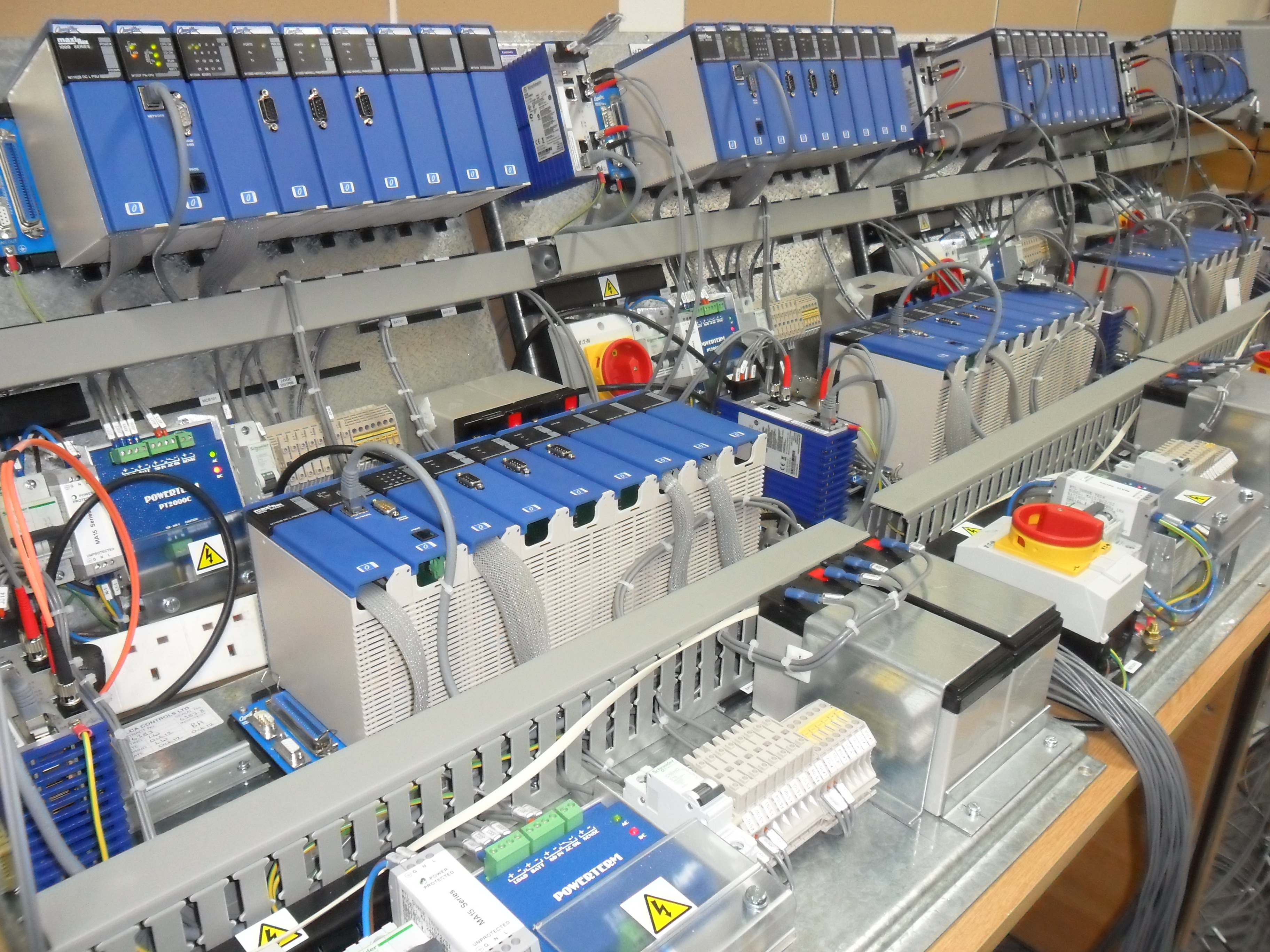
Control and instrumentation overlay for nuclear plants Posted by Darren Barratt on Thursday, March 19. 2026 Continue reading "Control and instrumentation overlay for nuclear plants"
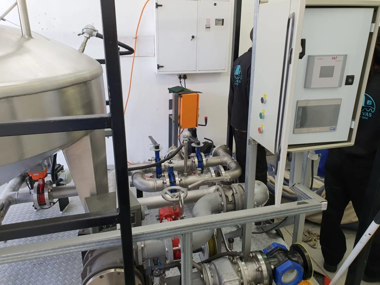
How to ensure flow measurement accuracy in oil and gas Posted by Darren Barratt on Thursday, March 19. 2026 Continue reading "How to ensure flow measurement accuracy in oil and gas"
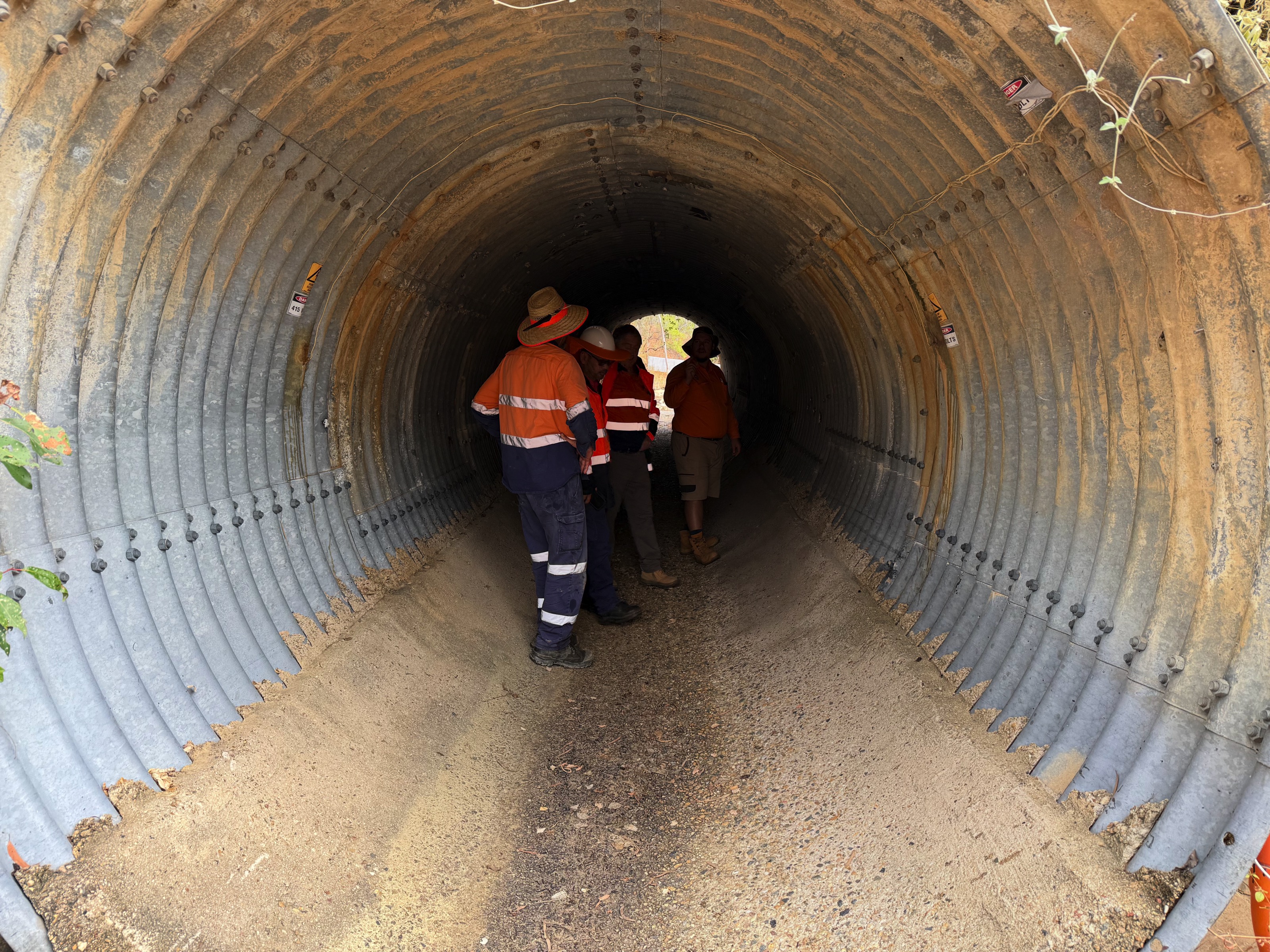
Managing remote infrastructure in harsh environments Posted by Darren Barratt on Thursday, March 19. 2026 Continue reading "Managing remote infrastructure in harsh environments"
Global Mobile Network Technology Changes – Decommissioning 2G,3G Services Posted by Darren Barratt on Monday, October 6. 2025 Continue reading "Global Mobile Network Technology Changes – Decommissioning 2G,3G Services"
Upgrading one of Australia’s first switch-mode CP installations Posted by Darren Barratt on Friday, October 3. 2025 Continue reading "Upgrading one of Australia’s first switch-mode CP installations"
Omniflex through the decades – The 1960s Posted by Darren Barratt on Friday, October 3. 2025 Continue reading "Omniflex through the decades – The 1960s"
Omniflex’s Maxiflex systems adds value to calibration in Africa Posted by Darren Barratt on Tuesday, May 20. 2025 Continue reading "Omniflex’s Maxiflex systems adds value to calibration in Africa"
Preventing nuclear events with remote monitoring Posted by Darren Barratt on Wednesday, April 23. 2025 Continue reading "Preventing nuclear events with remote monitoring"
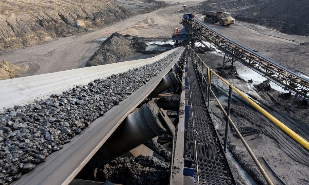
Boosting long-distance critical signal delivery in mining Posted by Darren Barratt on Wednesday, April 23. 2025 Continue reading "Boosting long-distance critical signal delivery in mining"
How CP system design can support ESG commitments Posted by Darren Barratt on Wednesday, April 23. 2025 Continue reading "How CP system design can support ESG commitments"
Assessing the order of events Posted by Darren Barratt on Wednesday, November 27. 2024 Continue reading "Assessing the order of events"
Simplifying battery management for dual voltage systems Posted by Darren Barratt on Wednesday, November 27. 2024 Continue reading "Simplifying battery management for dual voltage systems"
The role of alarm annunciators in temperature monitoring Posted by Darren Barratt on Wednesday, November 27. 2024 Continue reading "The role of alarm annunciators in temperature monitoring"
Kongsberg Maritime Alarm Annunciator Upgrade Posted by Darren Barratt on Thursday, November 7. 2024 Continue reading "Kongsberg Maritime Alarm Annunciator Upgrade"